Part 1: A wild hog appears!
Why my wife and I installed a thermal camera in our car
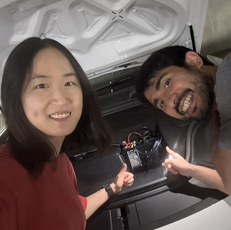
In the summer of 2024, my wife and I totaled our car in a collision with a wild hog driving to Yosemite. This blog series chronicles the engineering behind designing and installing a thermal camera system into our car (ala an ML-based animal detection system).
Where This All Started
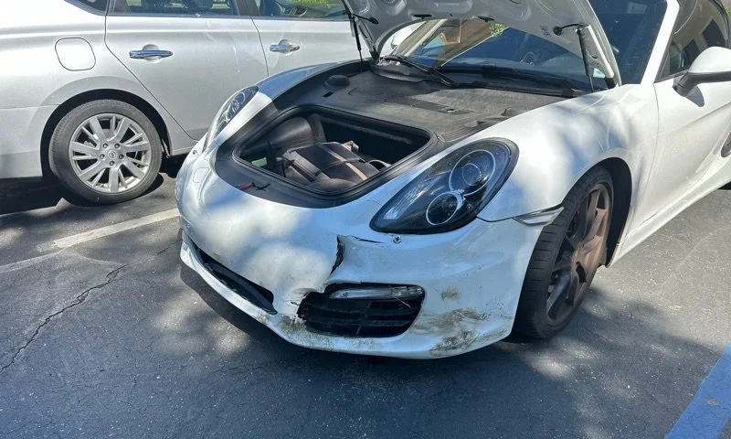
We were driving to Yosemite late at night when two wild hogs emerged from the darkness. We hit one, and the adrenaline spike was so sharp I could barely keep steady pressure on the accelerator pedal. The car was still drivable but leaking radiator coolant, and what on the surface looked like (in my overly optimistic mind at the time) minor body damage turned out to be possible frame buckling. Insurance totaled the car a few weeks later.
California's rural roads are basically an obstacle course after dark. And human vision is terrible at night - we see what our headlights illuminate, giving us tunnel vision with limited peripheral awareness. With a new car on order, we set out to design a thermal-camera based animal detection system to install so that this would never happen again.
Why Thermal & Camera Selection
We had a few design objectives in mind:
Must detect animals in complete darkness (we’re out hiking / camping in CA’s national parks at least several times a year)
Must work at highway speed (detection range > stopping distance + reaction distance)
Can’t break the bank; see BOM in a later blog post
Must integrate cleanly into our new car. No janky roof mounted contraptions, no extra screen to install.
This ruled out regular cameras out since they’d need active illumination to work at night. LIDAR looked to be too expensive, plus we’d need to figure out how to process point clouds instead of images. Radar the new car would already have - and we wanted classification in addition to detection (paper bag tumbling on the road vs. wild hog).

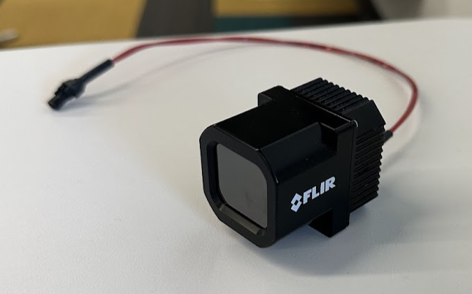
Thermal imaging hits the sweet spot. Animals are blobs of heat day or night, and FLIR makes an “Automotive Development Kit” camera that looked like it would be straightforward to integrate with a USB interface (see: https://www.flir.com/products/adk/)
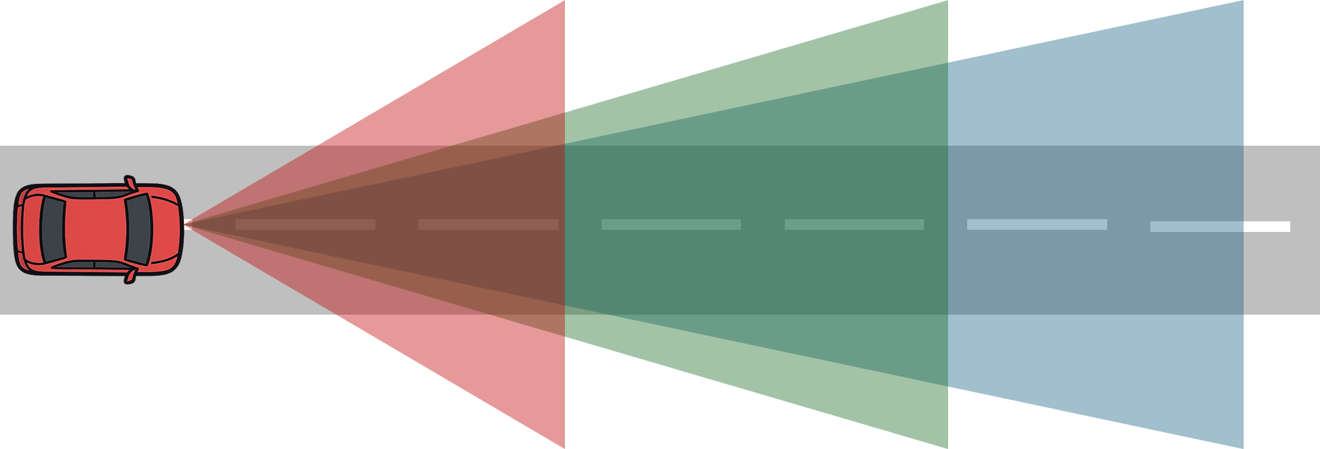
The FLIR ADKs operate at 640x512 and 60hz, which is on the high end for thermal cameras. Most consumer and industrial devices are 160x120 or 320x240, and anything higher resolution typically requires active cooling and more space than we had available for mounting. We picked one up with a 32 degree FOV. We narrowed down choices to 24, 32, and 50 degree FOV. The tradeoff is detection distance vs. peripheral awareness.
We figured we would want at least ~12 horizontal pixels for detection (eyeballed; felt like a reasonable span for ML), and at highway speeds needed that to happen sufficiently far out to brake in time.
A camera with θ degree FOV has a horizontal span at distance d of:
width(d) = 2d tan θ 2
The unit length per pixel (given Nx = horizontal pixels; 640 in this case) is:
Px(d) = 2d tan θ 2 Nx
If the real world horizontal span of an object is W, and we want at least p pixels horizontally across an object, then set this to p and back solve for distance
W = p 2d tan θ 2 Nx
d = W Nx 2p tan θ 2
Further assume ~250 ms human reaction time, and with the camera at 60 fps a further ~20ms detection time. Traveling at v m/s velocity, the available braking distance is now
d = W Nx 2p tan θ 2 − (0.25 + 0.02)v
Let Nx = 640 pixels, p = 20 pixels, W = 1 foot across for the average wild hog (0.3m), and with our new car’s braking distances:
| Speed | Estimated Braking Distance |
|---|---|
| 45 mph | 60 ft |
| 55 mph | 88 ft |
| 65 mph | 122 ft |
| Speed | 24° | 32° | 50° |
|---|---|---|---|
| 45 mph | 105 ft | 74 ft | 38 ft |
| 55 mph | 102 ft | 70 ft | 35 ft |
| 65 mph | 98 ft | 66 ft | 31 ft |
This ruled out the 50°, and between the 24° and 32°, we picked the 32° for slightly better peripheral vision and better pedestrian detection in urban driving. We figured we don’t drive particularly fast on rural roads anyways, and the ability to swerve vs. just brake also makes the 32° quite viable.
This camera does have a shutter, which means it triggers something called flat field correction “FFC” to normalize pixel readings - basically the shutter triggers, and is at a single uniform temperature to correct for any drifting pixels. This adds a bit of downstream logic so it doesn’t affect detection (more on this later). This also isn’t radiometric (capable of measuring absolute temperature vs. just relative temperature), but we figured we could come up with calibration curves ourselves if we wanted to.
Next up - compute and (some) electrical