Part 2: Compute & Some Electrical
This blog series chronicles the engineering behind designing and installing a thermal camera system into our car. Read the first post here.
Running Neural Networks on 12V
With a few grand plopped down on a new shiny thermal camera, the next challenge was processing power. The FLIR is capable of running at 60hz, and we wanted something that could run neural network inference in real time without melting itself or draining our car’s battery. And survive everything from scorching summer drives through California’s Central Valley to freezing winter trips to Tahoe.
The Power Reality
EVs in practice have both a high voltage and regular 12V low voltage battery. So despite our incoming car (EV) having a 95 kWh battery, we’d be tapping the (much) smaller 12V battery powering accessory systems - the same battery you’d wire a dashcam to or phone charger. We started mapping out constraints. Most 12V accessory circuits are fused for 10-15A, which translates to approx 120-180W of available power. But the thing with most car electrical systems is that they’re noisy. Every time you turn on your AC or even roll down your window you get voltage spikes and electromagnetic noise rippling through the system. Without an oscilloscope it would be hard to characterize exactly how noisy, but the point is we had to design for noise.
So we set a conservative target: 50W of total system power so there’d be sufficient headroom for any unexpected spikes. This was also intended to make thermal management easier downstream.
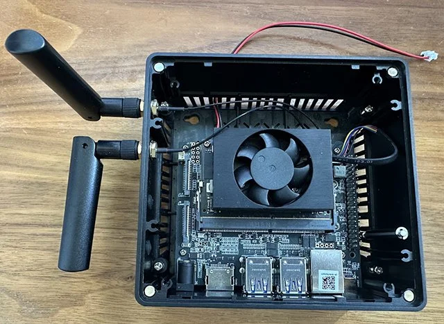
The Compute Platform
We landed on an Nvidia Orin Nano: 40 TOPS (!) at 15W of power. The chip was sufficiently reasonably priced that we could always upgrade to its bigger siblings - the NX (100+ TOPS) or even the AGX (200+ TOPS) - if we needed more power later.
Bulletproofing the Power Supply:
We picked up a MeanWell RSD60-G12 DC to DC converter, an appropriately spec’d (“Transient Voltage Suppression”) TVS Diode, and a small UPS that supports LiFePo4 batteries (for safety) so that we could cleanly shut down the Orin Nano vs. having power cut abruptly every time.
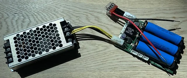
The car wires from a fuse tap to the MeanWell DC to DC converter (with the TVS diode across the leads), and then into the UPS and finally the Orin Nano.
TVS diode - protects against massive voltage transients by dumping power to ground past a clamp voltage.
MeanWell DC to DC - handles anything from 9V up to the diode’s clamp voltage and electrically isolates everything downstream.
OpenUPS2 - charges itself while the car is on, sends signal to Orin Nano via GPIO to shut down when the car is turned off, then waits 60 seconds before switching itself off. Can technically power everything for ~30 minutes if necessary.
10 Amp Fuse - part of fuse tap; last line of defense
Orin Nano - gets super clean 12V
Testing and programming the UPS (one day we’ll have an oscilloscope…):

With everything wired up on our workbench, we fired up our bench power supply to see how much power this thing actually pulled. We loaded up the Orin and made sure all cores were firing, put an ice cube on our FLIR’s heated window to trigger the circuit, and watched the power / current meter. The result? 30W total draw, even under full load
Theoretical Power Budget:
Orin Nano - 15W
FLIR ADK - 12W
IMU - 2.5W (has a heater)
OpenUPS2 - should be de minimis; mostly FET/conduction plus control overhead
MeanWell Efficiency - 86.5%
Overall = ~35W. 30W isn’t far off! All wiring is of the electrically shielded variety (USB cable to the FLIR ADK, power cables, etc), especially given potential proximity to high voltage wiring on an 800v architecture car.
CAD + Early Prototype of Mounting:


Next up - model training. Turns out ML is often 90% data wrangling 10% model training…