Part 4: Hardware Integration
This blog series chronicles the engineering behind designing and installing a thermal camera system into our car. Read the first post here.
3D Scanning, CAD, CNC & 3D Printing Parts
Mount Location
Our car’s front tow-hook area is thankfully large enough to fit the FLIR camera. To make the install seamless we’d just need to design a tow hook mount and refabricate the flap. The tow hook is also directly connected to the body chassis and conveniently oriented in the direction of motion.


3D Scanning Tow-Hook Area + Tow Flap
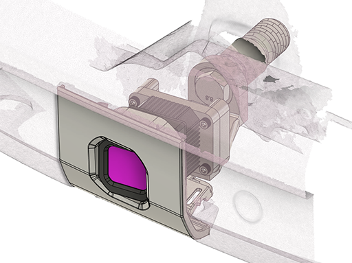
We worked with ScanSite up in Novato to 3D scan both the bumper and the tow flap. We wanted a 3D scan of the flap so that we could redesign it in CAD, and we planned to use the bumper scan to design the camera mount and align everything against the redesigned flap. (ScanSite was fantastic to work with btw!)


Left - 3D scan of bumper. Two Right - Tow Flap 3D solid model
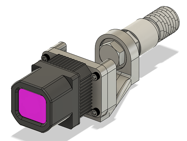
Designing & Manufacturing Everything
I miss SolidWorks and NX :( They unfortunately cost $$ and we couldn’t justify getting a license when Fusion 360 is free. Designing everything in CAD:
Detail of redesigned flap:


For waterproofing, we designed a groove for an o-ring. The part is complex enough that we’d need to get it 3D printed anyways, and 3D printing enables geometries that would be impractical to machine or injection mold. In this case the ability to design a dovetail groove into the panel. Here’s what this looks like (image from Apple Rubber seal design guide):

The o-ring and chamfer it sits in are designed for 20-30% compression based on our camera’s geometry and 3D printing tolerances. For material selection, the original part has “PP-T15-HI-UV” on it which we interpreted to mean polypropylene with 15% talc filler, high impact, UV stable. Given the complexity of the geometry 3D printing is the only viable option, and within 3D printing options given the tight tolerancing to get the waterproofing right either SLS or SLA. We guesstimated the original part’s flexural modulus to be around ~2 GPa, and found three materials we thought were decent matches:
Carbon 3D’s RPU 130 (could not find a bureau that could print in this so dropped it as an option)
Carbon 3D’s RPU 70
3D Systems Accura Xtreme
We got the part printed in both RPU 70 (Xometry - absolute hot garbage. Print was either in the wrong material or over-cured in UV) and Accura Xtreme (Protolabs - waay better, but to be fair we had them paint it in Cerakote C-138 Jet Black for UV stability and waterproofing):


Left - Xometry made Carbon RPU70 (RPU70 is supposed to have an elongation at break of 100%. The shiny clean break indicates this was either made in the wrong material or the part was over-baked in UV). Right - Protolabs Accura Xtreme in Cerakote C-138. The point of the Cerakote coating was largely to protect the part from UV-aging.
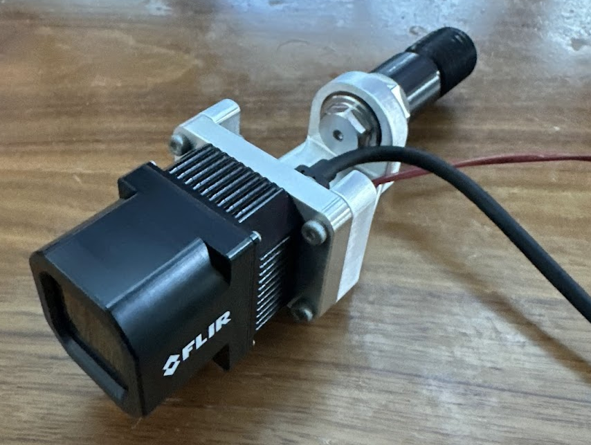
Designing the Tow Hook Mount:
3 parts to the tow hook mount -
Tow hook bolt (thank you @Matt for helping machine this) - mounts to car
Camera plate - mounts to camera
Camera jig - offsets and positions camera relative to tow hook bolt and flap
HLH Prototypes out of Shenzhen CNC’d the camera plate and jig (to the machinist out there that handled the monstrously non-DFM’d jig part like a champ - thank you lol):
Final Install:
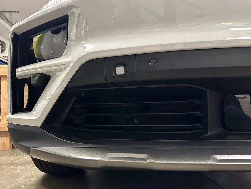
We got the color match of the replacement tow hook flap spot-on, but the texture’s very slightly off (imperceptible at most angles / distances). Our version is a fair bit smoother than the original part. If the flap ever gets damaged we might lightly sand-blast the next iteration to reproduce the finish but this is otherwise good enough for now.
Next up - Orin Nano to Car software architecture and client (phone) / server-side (Python) code